


The Wiring Diagram
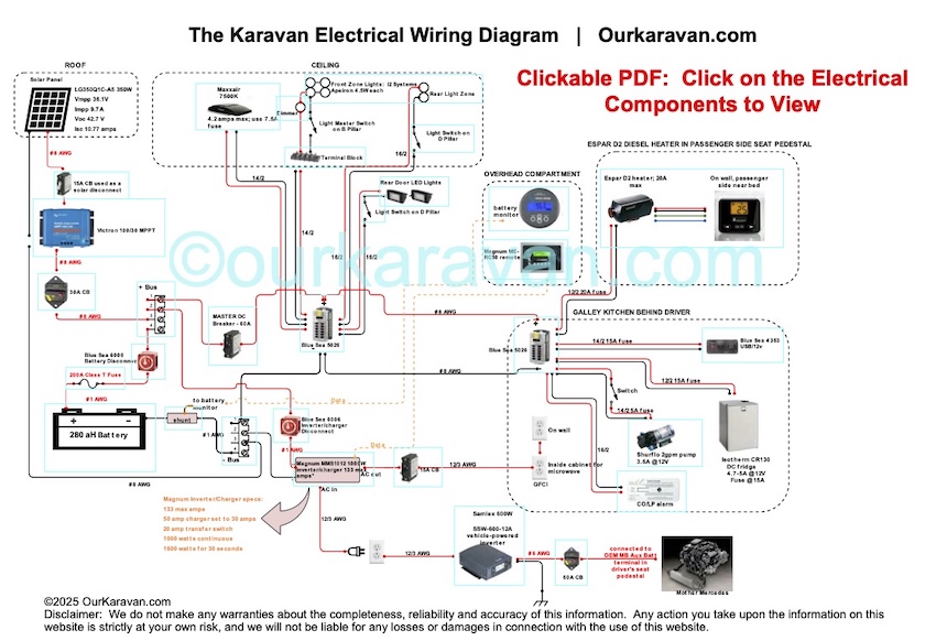
Below is an updated 2025 wiring diagram. Let’s get another thing out of the way; we are not licensed electricians, nor electrical engineers. We did a lot of research and use readily-available tools to help calculate the proper hardware and circuit protection for each load. In other words, this is OUR diagram for OUR van and we are sharing it with you. Swapping-out just one of the components with a different part may change the loads and therefore the required wire size and required circuit protection. While we have to say “Use at your own risk,” aside from a different battery, we have been using this system for 8 years now. Click the image below to enlarge.
Note:
For better resolution and to enable the web links, we recommend downloading the file. Right click on the above image and select “Download Linked File” or “Save Target as” or however your browser does it. Clicking on the electrical components in the diagram will load the exact products we used in our electrical system. Use of the affiliate links will not cost you a penny but will help support the continued existence of this website.
Two Wires to Every Load
Let’s start breaking-down that wiring diagram. The first thing you may notice is each device has two wires (a positive and negative). This is typical in a boat, but not necessary in a vehicle. In the age of over-sensitive and complicated vehicle electronics, it’s best not to use the body as a return path to ground. If you haven’t done a good job of wiring your van, the voltage traveling through your chassis ground can interrupt signals in your vehicle’s multitude of ECU’s (electronic control units), resulting in electrical problems. That’s why each load has its own ground that simply returns to the battery and is not touching the chassis. The house electrical system is electrically-isolated from the vehicle electrical system. This could be helpful in the event of vehicle warranty repairs. Ground problems are less likely to occur when wired in this fashion.
Following the Path of Electrons
Referring to the wiring diagram, power leaves the positive battery terminal and passes through a 200 amp Class-T fuse. Our 1,000 watt inverter alone could actually deliver 1,850 watts (155 amps) for up to 30 seconds. The fuse will protect the 1-AWG wire if there were ever a short in the main battery lead. The positive lead then goes through a 300-amp Blue Sea battery switch. This allows us to shut down power to everything connected to the battery with the turn of one knob. We turn this off when the van is not in use.
The Lithium Battery Management System (BMS)
The Battery Management System (BMS) is built-in on the Eco-Worthy batteries. It has the job of monitoring the cells in the battery for voltage and temperature. If a charging source went haywire and started overcharging the battery, the BMS will prevent further charging. If the battery dips to a low state of charge, the BMS will prevent further discharge to protect the battery. The internal BMS also prevents the battery from being charged at both high and very low temperatures.
Electrical Distribution (DC)
Now that power made it through our circuit protection devices, it’s time to go out to the loads. Power is first brought to a distribution bus, which supplies power in a secure, organized fashion to everything connected. (You will note that power lands here from the solar system and also distributes power to/from the inverter/charger.) Power then goes through a 60-amp DC breaker. 60 amps covers all of our DC loads assuming all devices were on at the same time. (Including some overhead.)
Next, power is delivered to the positive post of the first of two Blue Sea distribution (fuse) blocks. These hold 6 or 12 fuses and have terminals to provide circuit protection for the wiring behind it. The first one is located in the battery box to provide circuit protection for loads on the passenger side of the van and in the ceiling. Those items include the Maxxair fan, the overhead lighting and the LED lighting in the rear cargo doors.
Power leaves the first distribution block’s positive and negative posts and provides a feed for the second one located on the driver’s side behind the galley kitchen. This one powers the refrigerator, water pump, CO/LP alarm and some lighting. Of course power can also be fed to diesel heaters or any other electrical accessory in your van.


About Fuse Blocks
In a typical boat or RV you will find one circuit breaker/fuse panel. Wiring must reach from this hub to each electrical device. This centralizes the fuses to one location but lengthens and complicates wiring runs. In our build we have a fuse block on each side of the van to serve its respective electrical gear. The fuse blocks we used are rated to 100 amps and Blue Sea confirmed they can be in series as long as you do not exceed the amp rating. Our main DC breaker is a 60A, so clearly it would trip well before 100A would pass through the blocks. As stated, this is not a conventional approach but we think it offers some excellent advantages. One downside is the need to check two fuse blocks in the event of a device failure.
Fusing Each Load
For each “appliance” in the van, the manufacturer will recommend the size of the fuse that should be used. As an example, our Maxxair Fan can pull up to 4.2 amps and the manufacturer recommends a 7.5 amp fuse. Therefore, our Maxxair fan is attached to the screw terminals of the fuse block utilizing a 7.5 amp fuse. Each device has its own fuse, with a couple of small exceptions, all involving LED lighting. In those cases, we ran fused power to a terminal block (usually located in a confined space), then to the lights. This reduces wire runs and allows for multiple connections inside a tight electrical box.
Depending on the appliance, sometimes a switch is used in-between the fuse block and the device. This is the case for all of the lighting circuits as well as the water pump.
The negative side of the DC wiring is pretty much exactly like the positive side, with one exception. As the negative terminal leaves the battery, it passes through a device called a shunt. The shunt measures the energy passing through it and helps the battery monitor calculate the battery’s state of charge. It also displays real-time the amount of current going in or out of your battery. If 18 amps were coming in on solar and 5 amps going out, the monitor will display a net input of 13 amps on the display.
Battery Charging by Solar
Let’s talk about battery charging now. When the sun is out, the solar panel converts sun energy to volts and amps. A positive and negative wire enter the van from the roof and connect to a 15 amp circuit breaker. (Positive only.) Some argue this breaker is not needed, but we use it frequently to turn off the solar. The negative and positive wires then enter the Victron solar charge controller. The solar panel connects to the two screw terminals marked “PV” (one each for + and -).
There are two additional screw terminals marked “Battery.” The negative lead goes from the negative screw terminal of the charge controller to your negative busbar or negative battery terminal. The positive wire goes through a required breaker (30-amp in our case) to the positive side of your circuit. The power continues through the main battery disconnect switch, through the fuse and to the positive lead of the battery.
A Note about Maximum Power Point Tracking (MPPT) Solar Charge Controllers
You are probably wondering why the breaker before the solar charge controller is 15 amps and the one after it is 30. That’s part of the wonder of a MPPT (Maximum Power Point Tracking), which takes high voltage and turns it into lower voltage and higher amperage. The amperage leaving the charge controller will be higher than it came in, but voltage will be lower.
Battery Charging by Alternator (Indirectly)
We discuss the different ways of charging your battery by the van’s electrical system in this write-up. There you will read about why we chose an unconventional way of charging our battery from the van. Because the solar has done such a good job of keeping our batteries full, we are using a very simple and inexpensive solution. We have a small 600W pure sine inverter that takes 12VDC from the alternator (in simple terms) and turns it into 120VAC. Now that the voltage is higher, the amperage is reduced to around 5 amps. This reduces the wire size required down to 12 gauge. That size wire is actually overkill, but is way smaller than what would be needed if it were carrying 12VDC at 50-60 amps. Specifically, we used “12/3” wire, which means 12-gauge, 3 conductor. AC wiring generally has three conductors.
On the end of that wire is a standard 120V house duplex outlet located in the battery box at the rear of our van. Our Magnum 1000 watt inverter/charger is plugged in to that. When the inverter/charger gets plugged in to 120V shorepower, it automatically powers everything 120V in the van. It also automatically activates the battery charger and charges the battery. When we switch on the 600W inverter that is located under the passenger seat pedestal, it provides power to the outlet which makes the Magnum inverter/charger think it is connected to shorepower and our batteries are charged.
The Inverter/Charger System
We have one last system to discuss, and that is the 120V side of things. Battery power comes from the battery and travels through a battery disconnect switch. This allows us to disconnect the inverter from the rest of the electrical. We did this because the inverter has a draw even when it’s not running. In practice, it’s not enough to even be a drop in the bucket given the rest of our electrical system. The heavy gauge 1 AWG wire connects to two big power posts on the inverter. The inverter then converts that 12VDC to 120VAC. It passes through a 15-amp breaker and continues on to the 120V duplex outlets. One outlet is located in the back of a cabinet to power our microwave and the other is located adjacent to the galley for our electric induction cooktop.
That is the basic run-through of the electrical system in our van. I’m sure it doesn’t answer all of your questions and probably created more questions, but hopefully you find this helpful. Read on for tools in designing your electrical system.
Tools for Engineering your Electrical System
Start with our “systems planning” article and calculate your loads. Once you know your lighting uses 1.5 amps max, use the Blue Sea Circuit Wizard to calculate the recommended wire size for that load. Your circuit voltage is likely 12V, your load current is 1.5 amps and it wants to know the length of that wire to account for voltage drop. Assuming 4 feet of wire, it recommends AWG (American Wire Gauge) 18 wire. We recommend downloading the application to your Android or iPhone so you can make calculations while you work in your van. It also allows you to put that wire length and wire size back into the calculator to calculate the appropriate fuse or breaker size for that size wire. We can’t stress enough how important it is to fuse every load with the appropriate wire size and breaker or fuse for the given application.
Circuit Protection is for the Wire!
As a reminder, circuit breakers and fuses are your circuit protection. They are not intended to protect your device, they are to protect the wire itself. If you have a properly-sized fuse or breaker on a wire and it rubs through the insulation and goes to ground on the body (called a “short”), the amperage will increase and the breaker or fuse will open, and the circuit goes dead. If you have no circuit protection, the amperage will rise exceed the carrying capacity of the wire and proceed to melt the insulation and quite likely start a fire. You don’t want that. At all. As you are planning your wiring, just pretend each individual wire shorts somewhere in the middle. Do you have a fuse or breaker (the weak link) on that line? If not, it needs circuit protection.
Words can’t express how personally grateful I am for this article and diagram. For a couple weeks now I’ve grown increasingly frustrated with the lack of clear and concise information on electrical system design. For sure there is an absolute ton of information out there available, and while learning about it is great, at some point I just want to continue with the build. Your system is a great model to follow and by putting it out there, you have saved me weeks if not months of research and frustration. So thank you. What you are building here with your Van and your website is a massive asset to the community and the beginnings of something powerful should you continue to venture down this path…which I hope you do.
Thank you Bruno, I appreciate the nice words. Trust me, I spent countless hours trying to make sense of all of the electrical stuff. I recommend taking just one part at a time and studying that part until it makes sense. Do that for each of the components and you’ll have it all figured out. My goal is to try and clarify all the stuff that I spent forever trying to figure out. In particular, I found a lack of detailed information, including wiring diagrams, that shows how it all goes together. Anyways, thanks again for taking the time to write, I appreciate it!
Thank you for documenting your work and creating a valuable resource for others to use! Your wiring diagram is inspiring. I understand that you have wired all loads such that the negative returns directly to the battery negative. May I ask how/where your battery bank itself is grounded? Did you utilize a factory ground point in the rear of the Sprinter? Thank you.
Hi Jeff,
There is no chassis ground at all. If I were attempting to charge from the alternator, then a battery-to-chassis ground would absolutely be required to complete the circuit. However by using either a battery-to-battery charger or the inverter approach that I am using, the battery does not require such a connection to charge. Thank you for the kind words, I appreciate that!
Hi! Echoing what others have said. This is a great resource, thanks! I am just getting a start and will run a similar system as you but with a single AGM battery connected to solar and an inverter charger. No alternator charging.
I was happy to hear that it does not require a ground to the chassis. Why is that the case? Thanks in advance.
When charging by alternator, the chassis ground is required in order to complete the circuit. Batteries wouldn’t charge by alternator without that chassis ground. But when wired like a boat, where load has a positive connection and a return path to a busbar (which is turn connected to the negative battery terminal), the circuit is completed.
Thanks for posting this diagram.
A few questions:
1. If you weren’t using a BMS would the section of your diagram dedicated to the BMS (by the battery) basically be a positive bus? This is the part of your diagram that is the most unclear to me.
2. What housing are you using for your A-series breakers?
3. The Red LED lights you have in the MB housing….are they switched? According to the diagram they are not.
Thanks for all your help in the sprinter community.
Hi Jason, yes, if no BMS were present (and thus no contactors), then you could imagine those wires coming together at a busbar. When all conditions are normal, the contactors flow energy through them as if they weren’t even there. In the event of an undervoltage or overvoltage condition, the contactor will open to disconnect that part of the circuit.
The A-series are in a standard canex box from the home improvement store. I had to shorten the studs on the back of the breaker ever-so-slightly to get them in the box.
And yes, the red overhead is switched. Somehow that detail was missed when I was making the diagram. I use the red light far more than I thought. If I want to sit outside by the fire I can leave that on and it doesn’t disturb my sleeping child. It also preserves nightvision for when you’re in and out of the van.
Thanks for the message!
Great info! Getting ready to start my van build and thinking about electrical. I’d like to document it in a wiring diagram. What software or app did you use for your wiring diagram?
Hi Betsy, I used an online program called Scheme It, which you can find on Digikey’s website. Digikey mostly sells electrical components. I would prefer to use a simple drawing program but I didn’t want to purchase software just for the schematic. It worked out fine after a bit of a learning curve.
This is such a great article, I love the 600W inverter for charging off the alternator!
And really, your videos are the best by FAR! Very high signal to noise ratio and really well shot and edited.
I’ve watched too many looking for an “aha!” but the best you get is one or two useful pointers. I discovered your videos after I’d decided to use T-slot for cabinetry to control weight and give me more versatility over the wooden monsters.
Could you put a link to the over-voltage / undervoltage switches and the battery?
Thank you Patrick, I always appreciate the positive feedback. The battery is made by GBS but it’s getting more difficult to find them available from a company that will ship them. One place you can check is Battery Space in Richmond, CA. The contactors you can find by clicking on the “store” in the upper right corner and finding your way to my Solar and Battery section.
I’ve been super happy working with the 80/20. Just placed another order for some to finish up my rear cabinets. Enjoy your build@!
Hey Thanks for the response. Two final questions then I’ll quit bugging you.
The wire going into the 60 amp breaker for DC….is this 6 AWG?
Also, Your light switches on the b-pillar and those next to your dimmer…are they wired in a three way fashion? Also where did you source these switches. They are very cool.
Thanks again.
No problem Jason! the Blue Sea app says 6-8 AWG, but it depends on how long your wire run is. As far as the B-pillar and dimmer wiring, it’s pretty simple. Power runs through the dimmer switch. However I interrupted the ground wire to the dimmer by running it over to the switch on the B-pillar. This allows you to be able to switch the lighting on without having to get into the van, and likewise when you go to bed you can dim and kill the lights from bed (using the dimmer) without having to go to the B-pillar. It works great!
The B-pillar switch seems to be out of stock but this will at least get you the model number: https://amzn.to/2xJDaU8 Take care!
Ken, I think you have one typo in the article. Shouldn’t it state that the negative terminal (not positive) runs to the shunt? Great article otherwise, very helpful.
I found and corrected the typo, thank you for letting me know!
I just have to leave a comment about how helpful your videos and articles like the one above are! I have just placed an order for my 2019 144 Crew 4×4 and am venturing into a similar build as you have outlined. Your videos are amazing and extremely helpful and have embolden me to move forward and just do it! Thank you again for all the time you have spent to do this ……… you should open you own van build-out business as you could reap amazing rewards form your knowledge. Thanks again 👍
Rich, thank you so much for the thoughtful comment! So they are taking orders on the new models now? Congratulations and good luck with your build! -Ken
It seems you powered the the Espar from the vehicle/Aux battery. Do you need an Aux Battery to run this? Can it be run off the house battery?
You absolutely can, and most do power their Espar from their house battery. I mostly used the Mercedes Aux battery because 1) it’s there, might as well use it and 2) the aux battery tap is only a few feet away so it made for easy wiring.
Can you put a link for the BMS and the LCD? Thanks for all the great info, looks great.
Thank you! Yes, here is the BMS kit: https://www.batteryspace.com/lfp-bms-starter-kit-for-12-8v-lifepo4-prismatic-battery-pack-4-cells-with-lcd-screen-display.aspx
It comes with everything except the two contactors (which you can buy from them but they are cheaper at mouser.com. P/N Tyco EV200AAANA
Question on the battle born battery you recommend. You mention it has an internal BMS, but the amazon link doesn’t mention this at all. How does that work? Does this mean it comes with a monitor or? Their website isn’t great. I tried calling but they don’t answer the line.
Yes it does have an internal bms. I believe I linked to Battle Born’s article on how it works and what the bms controls. (over charging, low battery state, temperature, etc) Let me know if you are unable to find it.
There is no monitor, most people use the Victron bmv-712. It’s really good. I might have that number wrong but I believe I linked to it on the wiring diagram. I hope that helps!
You say you used the 80/20 because your woodworking skills are not great. If you were very confident in your woodworking would you absolutely choose 80/20 or wood (!) you consider building your cabinets out of marine grade materials/ply?
Love the diagram, really dig your whole production. Very thankful for you sharing your time and effort on this project.
Thank you Jody, I appreciate the nice comments. I would still use 80/20 even if I were good at work working. Part of working with wood is the skill, and part of it is very machinery intensive. Look around the shop of a good woodworker and they have table saws with sleds, jointers, planers, biscuit joiners, dovetail jointers…lots of large expensive equipment. 80/20 is just so practical in a van, from the sense that it’s easy to add things to the framing even after it’s built. And you don’t need much in the way of skill or equipment to pull it off. I really like the stuff. I need to find some new projects using 80/20 because I’m going to miss it!
I am truly impressed and thankful I found your website. After all my research, your system aligns with my plan and you did a great job making it clear and easy to follow. One question: the schematic shows for all LED lights switching is on negative rather than positive conductor. Why not positive?
Thank you Mike. I’ve seen DC circuits switched either way. Most DC automotive circuits switch the negative.
Hi Ken,
Once again asking a question gives me the opportunity to say how much I appreciate your contribution to our van builds ( mine is going slow, but progressing). My question is around your use of a terminal block to tie your LED lighting together into zones. Being challenged when it comes to visualizing electrical concepts has me scratching my head around the terminal block details. Seems to me, with each pair of screws isolated from the next, the only thing happening is the terminal block is basically just splicing the two wires together at the two screws adjacent to each other. I’m sure there is some detail I’m missing in understanding how you make this work. My plan is to have 2 or three zones that are dimmable and switched.
My build is a 2018 170 4X4 with 3 x100ah battleborns, 400w of solar with Victron 100/30 MPPT, and Multiplus compact12/2000/80/50 inverter charger. We have the factory aux. alternator bracket option and no aux. battery. Leaning toward going with a 280 amp dedicated Nations alternator to supplement the solar charging (could save our bacon during crappy weather like we are having in Alberta this summer), but am intrigued by your vehicle powered inverter concept and will look closer at it’s advantages.
Thanks again, and Safe travels
Gary, you have it right. A terminal block gets power and ground from the source and basically provides that same power and ground to anything you connect to it. If you were to take it apart, all the screws on the positive side are connected together with a bar, and all the screws on the negative side are internally connected via a separate bar. Rather than having multiple runs of wiring back to the battery for the lights, the block just distributes that power from one central location. The downside is one fused source provides the power, so if there were a problem with the circuit and the fuse were to blow you would loose power to all of the lights.
I consider the inverter to inverter-charger approach to be a backup system. from the standpoint that it is not automatic and I have to intervene when I want to use it. I found that in the first 1.5 years I had the van and no backup charging, I never needed anything but solar. I went ahead and added this backup system, and now that I’m almost 3 years-in, I’ve still only used it to test it and never because I actually needed it. Solar works amazingly well for me, but if you think you’re going to need alternator charging regularly, I would recommend a battery to battery charger instead.
Every time I look at your build i am even more impressed.
When looking at systems such as yours that use two inverters I have always wondered why you could not just connect your main inverter to the alternator? You would have to properly switch it or isolate it from the rest of your system when connected to the alternator but as you said because of your solar capacity you have never needed it. It is just a back up system.
The inverter is capable of 1000 watts but wouldn’t it just produce what is needed to charge your batteries?
Thanks.
The main inverter converts 120V back to 12V that the battery can use. It can’t take 14V from the alternator to charge, unfortunately.
Hey. Thanks so much for your videos and website, they have been one of my main resources while converting my sprinter. I took a lot of inspiration from your electrical layout. I just have one question: In one of your youtube videos you mention your PV panel outputs up to 40 Volts. The Blue Sea 15 Amp circuit breaker is only rated for 32 Volts. Has this been an issue? I’d like to have a breaker between my panels and the charge controller, but my panels output 62V 6A.
Hi, and thank you for the kind words. The specs for my panel claim a MPP Voltage of 32.2 Volts and an open circuit voltage of 39.8V. The typical operating voltage is around 28-29V as reported by the Victron app. Here are the panel specs if you’re interested: http://vdh-solar.nl/wp-content/uploads/Datasheet-LG300N1C-G4-Zwart-frame-wite-backsheet.pdf
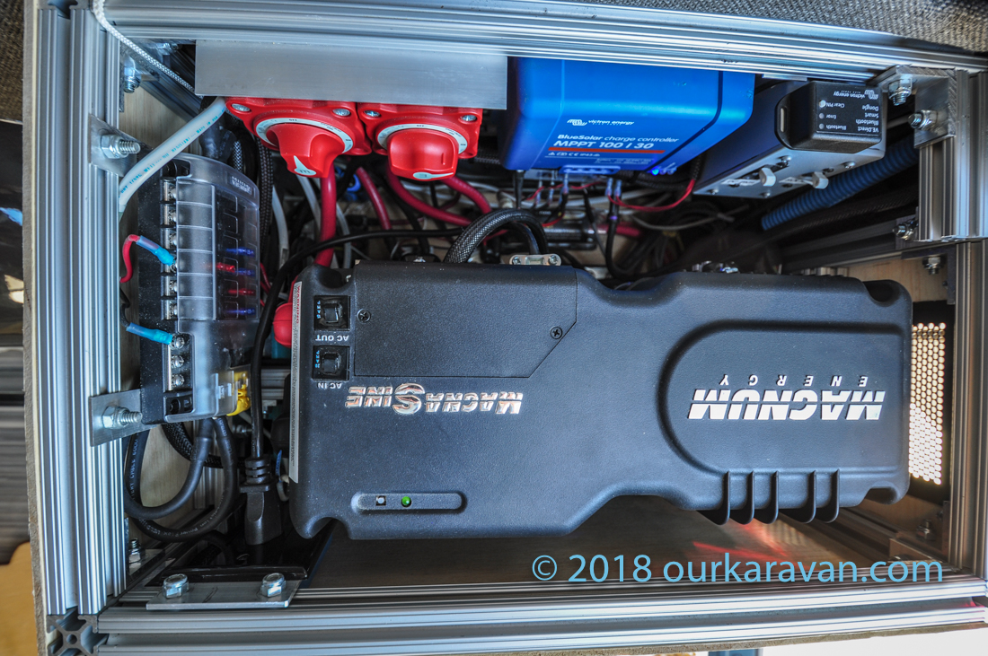
Hi Ken. Beautiful write-up. Can you provido some more socumentation on how you assembled your components in the box? I’d like to go the 80/20 enclosure route and I’m wondering: should I just use plywood walls or are there fasteners that I should get from 80/20?
Thank you Scott. In short, the 80/20 framing is attached to the walls and to the stock tie-down point in the rear corner. The battery and inverter are held down by some 80/20 that lay inbetween the two. Most of the components (fuses, breakers, etc) are simply bolted to a piece of 1/2″ plywood in the bottom of the battery box. The solar charge controller, breaker box and disconnect switches are simply bolted to pieces of aluminum angle attached to the 80/20. Very simple. I hope that helps.
Hello Ken, First I want to thank you for documenting your build so well, it has been a huge help to me in building out my van! Quick question on the perforated metal panel on the back of your electrical box, I’ve been looking for one and so far no luck, can you direct me to what you used, or maybe some google search terms?
Thanks again for all your hard work in sharing your build! May God richly bless you and your daughter.
Hi Larry,
Ha, you’re right, it’s all about search terms. Who would think you need to type “Penn Elcom perforated dish?” I have purchased them from both Amazon as well as Parts Express.
Thank you for the kind words!
Ken
Thanks so much Ken!
Larry
Hey Ken,
I wouldn’t be bothering you if I wasn’t driving myself crazy and hadn’t spent 3 hours trying to find the answer. I have a Lithium BIM for my 100 AH Lithium battery. You mention that to charge from the alternator like this that the House battery negative needs to be grounded to the chassis. I don’t entirely understand why, but my question is what gauge wire would I use and where do I run it? I know there are all the chassis grounding location on the sprinter, for instance, under the driver seat, but this doesn’t seem like a location where you’d run a large gauge wire to. Can you provide any clarity to that question?? Thanks so much
Hi Mike, if you are using the chassis alternator to charge the battery you’ll need a chassis ground to complete the circuit. Otherwise no charging would occur. Wire gauge will depend on the load. Once you determine the maximum amps passing through that cable, you can use an online calculator to help you calculate the wire gauge. I have a write up in the electrical section of this site that tells you how to do that.
Because I don’t have a chassis ground I’m not familiar with the locations of the grounding lugs. Sorry on that one!
Hello Ken,
Is it possible to wire the van with more battery capacity? Would I need more capacity for the solar panels?
You can always add batteries for more capacity. Some people need 800 amp hours, others make-due with 100. Because we are space-limited with a van, the general rule on solar is to put as much on the roof as you have room for, also taking into account whether or not you require roof storage. I hope that helps!
Hi again Ken – your dc wire is 8 gauge while your breaker is 60. Isn’t 8 gauge rated for 40 and thus you should use a 40 amp breaker? Thanks!
Hi Jason,
Ampacity charts show AWG 8 rated for up to 80 amps, but that number drops as wire length and temperature increases. The Blue Sea circuit wizard shows AWG 8 for 60 amps continuous for ampacity, but AWG 6 for voltage drop. You can use AWG 6 if you prefer, but particularly if you’re using lithium batteries with a higher resting voltage, the voltage drop won’t be a concern. Thanks Jason!
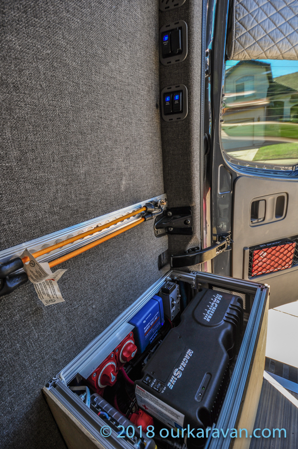
In the last photo, in the rear van door pillar, you have what look like some nice 3d printed inserts, do you have the stl available for download somewhere?
Hi Alex,
Those are actually the factory plastic plugs that are used in the crew vans. If you go to my store, scroll half-way down and you’ll see the MB plugs listed: https://kit.co/ourkaravan/electrical-distribution-fuses-breakers-wire
I simply cut holes and added switches into the blanks.
Hi Ken – I used your electrical plan, thank you so much! Can you let me (us!) know why you use A-Series circuit breakers for most thingsbut a single Blue Sea B-Series between MPPT and + bus?
Hi Henry, it came down to packaging. In this case it was more convenient to mount the B-series on the floor of my battery box. -ken
Ken, thanks for the awesome information and videos they are both informative and entertaining. I feel like I must be missing something on the electrical. It looks like when you have shore power available you just move the Magnum Inverter 120V powder cord from the outlet (fed by vehicle power inverter) to the shore power box. Am I missing something? Also, I’ve never had an RV but understand camp sites have 30A or 50A connections. I assume they also have 120V outlets? If not I guess you need an adapter?
Also, I plan to have essentially the same items the require power in my van, only I will have AC. I would plan to only use the AC if I had shore power. So I’m thinking if your system works they way I think it does and you just plug into 120V outlet for shore power. I should be able to have a separate powder cord for the AC? Thoughts?
Hi Craig, you have it correct. My inverter is typically plugged into a duplex outlet that comes from the vehicle inverter. If I wanted shore power I would simply unplug from the duplex outlet and plug into an extension cord to a 120V power supply. If a person wanted to do this regularly you could simply have a sealed shore power plug somewhere under the van that comes up into your battery compartment and either put it on a selector switch or use the plug/unplug method I use. Doing it this way eliminates the need to run an extension cord out a window or door. I never need shore power so I haven’t bothered.
Most shore power pedestals have a 120V duplex outlet in addition to a 30/50 amp supply. I’m not familiar with what’s available for RV air conditioning so I can’t comment there, but I see no reason why what you’re proposing wouldn’t work.
I hope that helps! -Ken
hi Ken,
you have done a tremendous job on your conversion and provided great service to the growing community of DIY’ers, so Thank You. I admire the compact, level of detail, choice of materials and tools and your website is by far the best one out there.
I have a question regarding your electrical system as you have incorporated some unique solutions, including the inverter off alternator to charge battery logic. I am however very interested in your logic behind the grounding. It appears that you did not ground anything in the DC system other than the previously mentioned inverter. Can you expand a little on that logic?
Hi Peter,
To start, thank you, very appreciative of the nice comments. The van is basically wired like a boat–with two wires to each load, each positive connection landing on a fused distribution block and each negative on ground bus that ties back to the battery. You are not relying on the chassis to act as the ground. They say that modern vehicle electronics, which also use the chassis ground, are so sensitive that introducing all your house electrics onto the same ground plane can be problematic. It’s also easier to track down any problems with either the vehicle or your house system if they are kept separate. I think it makes for a more reliable electrical system. I hope that answered your question! -Ken
Probably a stupid question… I’m coming at this from a novice point of view!
I’m planning on using marine wire and understand crimping etc
I was planning on using one size wire for my DC circuit, when joining to a switch or an appliance with smaller wires/connectors what is the best method for this? I’m guessing in an ideal world, you’d have a “correctly” sized wire going back to the fuse box and then it’s not an issue?
The build/website/youtube channel is such a great resource. Thank you!
Lots to talk about here. The wire size should be able to carry the max load of everything connected to it. Each device really should have its own run from a fuse block. As an example you can run large gauge wire to a fused distribution block, then run smaller gauge wire from each connection point on the fuse block to the load.
Ken, thank you so much for your detailed info… I just have a few questions. I have a sprinter 3500 xd and have had a roof Houghton AC unit installed with a 30A plug and wish to use 600Ah lithium batteries and 3000 watt inverter… besides the obvious of adding the 30A input from the shore, would anything else change like wire size etc from your wiring diagram? Again thank you!
Yes, wiring size will definitely change. A 3,000 watt inverter can pull 3X the amperage in normal use and possibly more in surge. You’ll need significantly larger cables. The length of the cables is a factor too. You can use the Blue Sea circuit calculator to help calculate the appropriate wire gauges. -Ken
Ken: How about a Bluetti AC200 Max ( https://www.bluettipower.com/products/ac200max-power-station ) which is expandable, or a Goal Zero Yeti 3000x . These seem compact and swappable, and possibly cheaper? What do you think of these new all-in-one offerings?
I don’t have any direct experience with it but check the Will Prowse YouTube channel. He takes these power packs apart all the time and does some really detailed reviews.